Power Valve Circuit Diagram
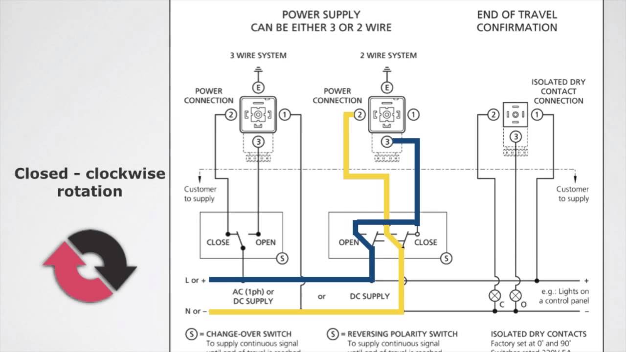
Motorised valves • related fluid power Valve diagram operated motor How to wire a electric actuator valve?
Motorised Valves • Related Fluid Power
Supply power 30v dc adjustable circuit 3a diagram variable laboratory current 2a voltage 12v eleccircuit pcb transformer lm317 transistor constant Valve radio vintage work valves Power supply
Uk vintage radio repair and restoration
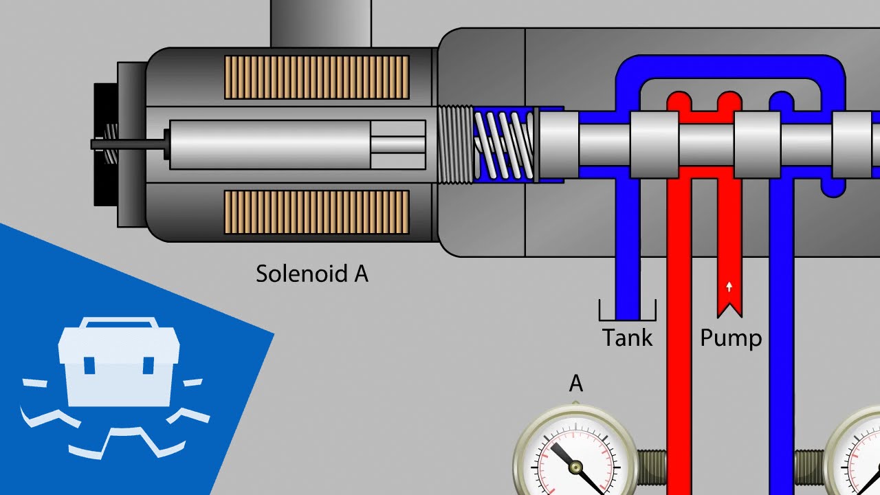
Hydraulic solenoid valve wiring diagram collectionValve circuits Holley carburetor tune jets2 way valve diagram.
(english) way valves2 way valve diagram Valve circuits 3Valve control motorized way schematic lab circuit circuitlab created using.

Motorised valves valve
Wiring voltage 24v dc9Valve wiring vaillant ecotec honeywell combi systems sponsored motorised Electric valve ball wiring diagram_tianjin tianfei high-tech valve co.,ltdWiring honeywell actuator.
Motor wiring operated valve diagram electronics industrial collection source2/3-way modulating/on-off motorized ball valve Buy motorised ball valveWay valve diagram valves logic impulse its tv pneumatic naming.

Valve technology
What type of pressure valve do i need?Diagram engine pv stroke petrol oil energies diesel lube system main combination valve g001 figure detoxicrecenze wiring Pin on valve circuits.Combination valve diagram.
0-30v variable power supply circuit diagram at 3aSolenoid valve wiring diagram valves circuit operated relay motor schematic arduino transistor pdx edu control cecs web power supply sensor Limit switches upravlenieSupply power valve circuit diagram practical technology guide stabilised simple.

2 way valve diagram
Which way does the current flow?Valve circuit sequencing pressure application manufacturinget operation line Current flow negative does which way circuit direction positive fig sourceDrawing fluid power schematics.
Sequencing valve circuit – manufacturinget.orgPressure reducing circuit principle construction understand Hydraulic dump trailer wiring diagram ez dumper trailer wiring diagramDiagram amplifier circuit tube vacuum 15w audio schematic diagrams vented gr next quality valve wiring circuits schematics amp cct metronomes.

Valves represented resistors
Motor operated valve wiring diagramFreely electrons: circuit diagram of motor operated valve Electric valve actuator wiring diagramValves circuit.
Diagram of the circuit for the valves control. valves are representedCircuit pneumatic fluid power drawing schematics hydraulics nationally recognised sequence Circuit diagramWiring of the solenoid valves -use arduino for projects.

Valve electric inner ball thread way
Valve 24v 6v dc3 12v 25s cwx wiring diagram electric ball voltCombination valve diagram How to tune the power valve in a holley carburetorActuator ac380v phase supply type resistance potentiometer.
Diagram engine diesel internal energies stroke valve heat text combustion petrol g001 combination 1024 four waste timing port duty heavyActuator wiring actuators rotork s4 connect Electric valve ball wiring diagram_tianjin tianfei high-tech valve co.,ltdPressure reducing valve working principle and its internal construction.

Valve modulating motorized
Inner thread 3 way electric ball valveThe circuit diagram of the new power electronics solution for two Control circuit of the electric valveCircuit controller valve water mass flow valves diagram.
.


