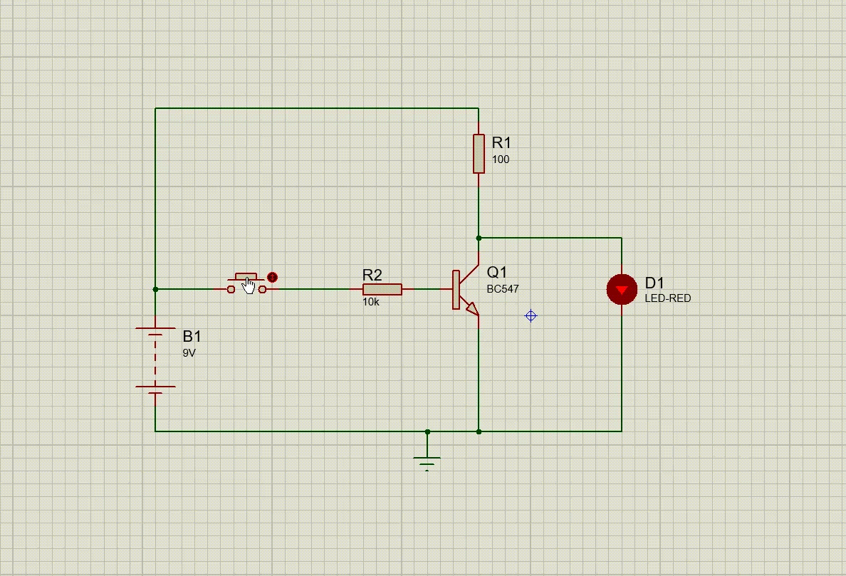
Not Gate Circuit Diagram Using Transistor
Transistor transistors npn truth logic bipolar circuits diode circuitdigest Designing an and gate using transistors How to build a not gate with a transistor
LOGIC GATES USING TRANSISTOR – NOT, AND, OR » PIJA Education
Gate signal transistor circuit invert inverter diagram using logic ttl schematic arduino bjt electronics simple create gates pinout ic robot Working of not gate using transistor Gate transistors using schematic mosfet implementation why two circuit circuitlab created
And gate diagram transistor
Digital logicTransistor breadboard etechnophiles Nor transistor transistors resistor logical parallel connected junction bipolarSchematic transistor gate circuitlab created using.
Nand gate implementation transistors circuit diagram electricalTransistors transistor nand Digital logicTransistor logic npn.

How to make resistor-transistor logic gates
Nor gatePin on logic gates using transistors How would you set up a circuit to obtain not gate using a transistorTransistor gate using circuit obtain would set given seen below figure.
Transistor gate inverter logic gates circuit diagram gif ttl petervis usedNot gate circuit diagram on breadboard Logic gates using diodes and transistorsTransistor in the not gate.

How to make a not gate on breadboard using a transistor
Gate transistor logic npn schematic diagram using circuit wiring practical questions circuitlab created stackGate circuit diagram electrical4u transistor principle working Logic gates using transistor – not, and, or » pija educationElectronics projects: how to create a transistor not gate circuit.
Gate transistor circuit using logicGate transistor using circuit diagram improved schematic designing version circuits And gate using transistorGate transistors using build circuit schematic logic make digital switches circuitlab created electrical.

Designing an and gate using transistors
Simple nor gate (transistor-level) diagram – valuable tech notesTransistor not gate circuit Transistor logic not gateNot gate: how does it work? (circuit diagram & working principle.
Using diodes circuit logic gates gate output input must transistorsTransistor logic circuit electronics gerbang bjt npn gates circuits inverter ttl transistors rtl electronic schematic gatter nor saturation logika collector Digital electronics-logic gates basics,tutorial,circuit symbols,truthWorking of or gate using transistor.

Gate transistor circuit logic two input high course know has electroniques zpag english
Gate transistorsDigital logic Designing or gate circuit using transistorTransistor logic resistor gate gates make maker pro transistors nand two.
Not gate circuit diagram using transistorAnd gate using transistor Gate transistor input logic gates output circuits digital diode circuit transistors truth nand led build made questions different current electronicsTransistor or gate.

Is this npn transistor and logic gate practical?
Designing an and gate using transistorsTransistor npn gates electronics circuit logic transistors Implementation of a not gate with two transistorsGate using transistor circuit transistors.
Gate transistor circuit transistors resistorElectronic – implementation of a not gate with two transistors – why Three different types of circuit diagrams, one with an on and the other.


